AR® Windamper®
Galloping and Vibration Control for Single Conductors
Overhead Transmission Lines & OPGW
Applications
Controls galloping of a single conductor by using the aerodynamic lift and drag to cause variation in the wind angle of attack along the conductor. This action creates stability for the entire span by reducing or eliminating galloping motion. The Windamper® has eliminated breaker operations on treated spans and at switchyards, connected to the treated spans.
Since the severity of the galloping phenomenon is a function of span length, sag, conductor geometry, and mechanical properties, each Windamper system is engineered to address the unique features of the line. Over 15000 units have been installed on spans of 500’ to 1800’.
The Windamper is available in several models to accommodate various span lengths, including corona models for transmission lines of 230kv and above. It May be installed by helicopter on hotlines at voltages up to 345kV
How it works?
Twisting Mechanism. Windamper is engineered to introduce positive damping through aerodynamics. Twisting is the principle design element of the Windamper. By twisting at the attachment point to the conductor, the Windamper® uses gravity and wind force to induce twisting
when galloping occurs. This twisting about its long axis effectively cancels the aerodynamic lift caused by any ice layer formed.
Reliability. For more than 40 years, the Windamper® has been protecting long spans, hard-to-reach locations (river crossings), power lines serving large manufacturing operations (steel mills), and the nine circuits serving Niagara Falls.
Safety. Protects transmission equipment from catastrophic failure and surrounding facilities from collateral damage.
Galloping Control. Controls galloping by using aerodynamic lift forces to twist the conductor, change the angle of attack, and arrest galloping. Twisting is a proven technology and method for galloping control.
Performance Tested
Tested at MIT for wind blowback and rotational vibration, the Windamper® remained stable and without vibration in wind speeds up to 50mph. AR®Clamps (attaching the Windamper to the conductor) have been strength tested at Helical Line Products. Slipping tests found clamp strength to exceed 2000 lbs.
Specifications
48” and 72”
Nutcracker design; 20 sizes scaled for conductor outer diameter
5/8” nuts/bolts/washer for clamp assembly
5/16” nuts/bolts/washer for bracket/panel assembly
breakaway bolts supplied for installation on Alumoweld OPGW
as required
Construction
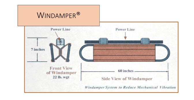
Fabricated of aluminum throughout, the Windamper® may be fitted with corona protection as necessary. It is available in two lengths – 48” and 72”; weighs 22 lbs. and 33 lbs. respectively. In service for more than 40 years, the Windamper® has been demonstrated to be the most cost-effective galloping control solution for single-conductor spans of 700 ft. or longer.

Each Windamper unit consists of two panel/bracket assemblies, two clamps and hardware. Field assembly necessary to join the two panel/brackets before attaching the clamps to the assembled damper during installation on the line. Armor Rods are required.
Windampers may be installed on Optical wires; application used break-away bolts and the damper is installed at 22-23 ft. lbs.

Note: The Windamper® is designed for use with Armor Rods over the conductor only. Armor Rod specifications will be included in the recommendations for the galloping solution together with specifications for the Windamper® model, a number of units, and placement on the line.
